How can the properties of a material really be determined reliably?
In materials testing, many methods reach their limits when it comes to precise characteristic values. This article explores the world of materials testing through destructive materials testing and shows why these methods are indispensable in quality assurance and development. It offers fascinating insights into mechanical properties, chemical analyses and the differences between the various test categories.
Destructive materials testing is carried out on standard-compliant specimens in order to make reliable statements about material properties. These methods provide characteristic values that cannot be obtained in any other way. Laboratories with test procedures accredited to DIN EN ISO/IEC 17025 carry out these investigations in accordance with the standards.
From mechanical engineering to welding technology, numerous industries benefit from these analyses. Specimen production and testing are completed in a short time. What exactly makes these methods so valuable for manufacturing and development?
-
- Destructive testing methods provide precise characteristic values on the mechanical properties of materials through the targeted destruction of specimens
- Laboratories with test procedures accredited to DIN EN ISO/IEC 17025 guarantee standard-compliant and legally binding test results
- The distinction between worker tests and procedure tests enables application-specific quality control
- Materials testing by destructive testing is indispensable in sectors such as mechanical engineering, pressure equipment construction and steel construction
- Fast turnaround times of 2-4 working days support efficient production processes and quality assurance
- Despite the destruction of the test pieces, these methods are often the only way to achieve reliable material characterisation
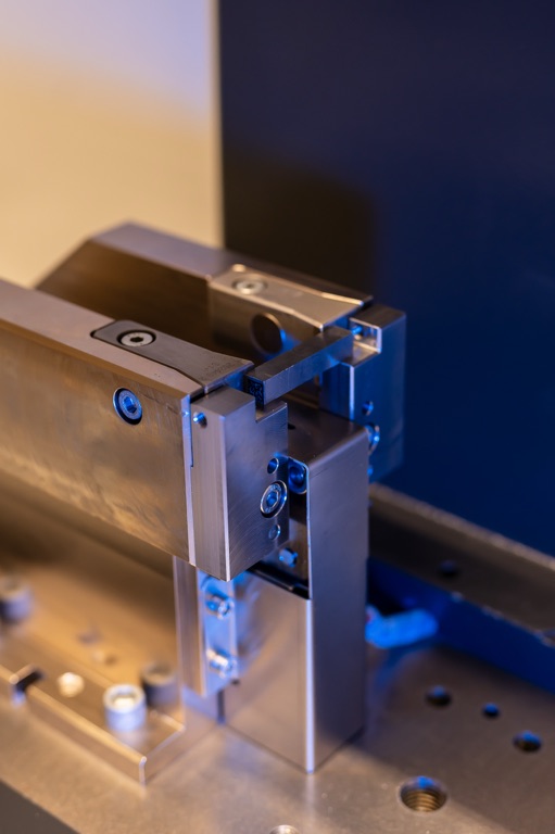
Understanding destructive materials testing
Destructive materials testing is among the most important tools for examining materials thoroughly. It provides exact data on the internal structure and load-bearing capacity of materials. Unlike non-destructive methods, the specimens here are deliberately pushed to their limits.
These test methods are indispensable for industry and research. They help to guarantee safety and quality in manufacturing. Standardised procedures produce reliable results that are comparable worldwide.
Fundamentals and working principle of destructive test methods
In destructive materials testing, specimens are deliberately loaded or altered. The aim is to determine the properties of the material. The specimen is stressed so heavily that it loses its original shape or fails completely.
This “destruction” is by no means random. Every test follows a precisely defined protocol. The test conditions are described in national and international standards.
For example, tensile forces, compressive loads or temperature fluctuations are applied. The reaction of the material provides information about its mechanical characteristic values. These include strength, deformability and fracture behaviour.
A major advantage lies in the precision of the measured values. In contrast to indirect measurements, destructive materials testing reveals the actual failure behaviour. This information is particularly important for safety-relevant components in power plants, bridges or aircraft.
Worker tests and procedure tests compared
Worker tests assess the skills of welders and operators. The person to be tested produces a welded specimen under specified conditions. This specimen is subsequently examined destructively.
The most important standards for worker tests are:
- DIN EN ISO 9606 for welder qualification tests in various material groups
- DIN EN 1418 for operator qualification in plastics welding
- DIN EN ISO 14732 for welding personnel qualification
- DIN EN ISO 17660 for aptitude tests in reinforcing steel welding
Procedure tests, on the other hand, qualify complete manufacturing processes. Here it is not the person but the entire welding procedure that is validated. The test is independent of who later carries out the work.
Relevant standards for procedure tests include:
- DIN EN ISO 15614 for welding procedure tests in metalworking
- AD 2000 HP2/1 for pressure equipment construction and welding procedures
- DIN EN 1090 for load-bearing steel structures and aluminium structures
This separation ensures clarity in quality assurance. A qualified procedure guarantees reproducible results. The worker test ensures that the personnel possess the necessary skills.
Practical applications in industry and research
Destructive materials testing is used in many areas. Its versatility makes it a universal tool for quality control.
In quality assurance, these tests help to monitor production batches. Random samples from ongoing production are taken and tested. The results show whether the material quality meets the specifications. Acceptance certificates for customers are often based on such tests.
In materials science, destructive methods enable the characterisation of new alloys. Researchers develop improved materials with optimised properties. Without precise testing, targeted further development would not be possible.
In failure analysis, the tests provide important clues to the causes of failure. After a component fractures, specimens are taken from the damaged area. The investigation shows whether material defects, overload or manufacturing flaws were present.
Concrete examples of use can be found in various sectors:
- Pressure equipment construction: Every pressure vessel must meet the highest safety requirements, in accordance with the Pressure Equipment Directive 2014/68/EU.
- Steel construction: Load-bearing structures such as bridges or halls require tested joints in accordance with DIN EN 1090.
- Rail vehicle construction: Safety-critical components undergo extensive materials testing before approval.
- Automotive industry: Crash test analyses use destructive methods to assess vehicle safety.
The insights gained feed directly into improvements. They increase safety and extend the service life of components. This is why destructive materials testing is economically worthwhile and technically indispensable despite the loss of material.
Mechanical destructive test methods
When it comes to determining the load-bearing capacity of materials precisely, mechanical destructive test methods are used. These tests simulate real loads and provide reliable characteristic values for design and quality assurance. The specimen is deliberately loaded until failure – only in this way do materials reveal their properties.
The range extends from static tests to dynamic load scenarios. Each method targets specific material properties and complements the overall picture of the material characteristics. Modern testing machines record the measured values precisely and document the entire loading sequence.
Tensile test for determining mechanical characteristic values
The tensile test is regarded as the standard procedure in materials testing and is among the most frequently performed tests. A standardised specimen is clamped in a universal testing machine and pulled apart continuously. The machine records force and elongation up to the fracture of the specimen.
Universal testing machines cover load ranges from 2 to 1000 kN – depending on the material and specimen dimensions. Smaller machines are suitable for plastics or thin sheets, while large systems test massive steel specimens. The versatility of these devices makes them the workhorse of every test laboratory.
During the test, important characteristic values are obtained that describe the material behaviour:
- Yield strength or proof strength – marks the transition from elastic to plastic deformation
- Tensile strength – the maximum achievable stress before fracture
- Elongation at fracture – shows the deformability and ductility of the material
- Reduction of area – characterises the lateral contraction and enables the determination of the Z quality
The stress-strain curve visualises the complete material behaviour. It clearly shows how the material behaves under increasing load. Engineers use this curve to dimension components safely and minimise failure risks.
The Z quality is of particular importance for welded structures made of thick-walled sheets. It describes the ability of the material to absorb stresses perpendicular to the sheet surface. A high reduction of area of more than 35% signals good weldability and a low risk of lamellar tearing in accordance with quality grade Z35 to DIN EN 10164.
Bend test for ductility and formability
The bend test examines how well a material can be deformed without breaking. This test is indispensable particularly for welded joints. The specimen is bent around a mandrel of defined diameter – this reveals lack of fusion and cracks.
There are various bending types for different test objectives. Transverse bending loads the weld seam transversely to the welding direction, while longitudinal bending acts parallel to it. Side bending concentrates on the weld flanks and the transition zone to the base material.
A special case is the weld bead bend test for bridge steels. Here a weld bead is applied to the specimen, which generates residual stresses as it cools. The subsequent bending tests whether the material can stop crack propagation – a critical property for safety-relevant structures.
The bending angle and the number of bending cycles document the formability. Highly ductile materials can be bent up to 180 degrees without showing cracks. Brittle materials fail at small angles, which indicates limited possibilities for use.
Notched bar impact test according to Charpy and Izod
The notched bar impact test measures toughness under sudden loading. A pendulum impact tester strikes a notched specimen at high speed. The absorbed impact energy characterises the resistance to sudden loads.
Pendulum impact testers with working ranges from 300 to 750 J test standard notched impact specimens made of metallic materials. For very small specimens from weld seams, thin sheets or plastics, devices with 25 J or 50 J are used. The energy is measured in joules and provides information about the impact toughness.
Two methods dominate in practice:
- Charpy method according to DIN EN ISO 148-1 – the specimen rests on two supports, the impact occurs opposite the notch
- Izod method according to ISO 180 – the specimen is clamped at one end, the impact strikes the notch side directly
The temperature dependence of toughness is a decisive aspect. Many steels exhibit a transition from ductile to brittle fracture behaviour at low temperatures. Tests between room temperature and -100 °C capture this transition range, while tests down to -196 °C simulate extreme cold conditions.
The notch shape significantly influences the result. V-notches to ISO standard or U-notches generate different stress concentrations. The choice of notch geometry depends on the material and the question to be answered.
Fatigue strength test under cyclic loading
The fatigue strength test simulates cyclically alternating loads from practical operation. Components such as crankshafts, springs or bridge girders experience millions of load cycles during their service life. This test determines the load limit at which a technically infinite service life is achieved.
Fatigue testing machines load the specimen with constant amplitude between upper and lower stress. The frequency is typically between 10 and 100 Hz. Tests run for weeks until the specimen fractures or the limit of 10 million load cycles is reached.
The Wöhler diagram presents the results graphically. It shows the relationship between stress amplitude and the number of load cycles that can be withstood. Three ranges characterise the fatigue behaviour: low-cycle fatigue, finite-life fatigue and fatigue strength.
Various types of loading are applied. Tension-compression alternation simulates symmetrical loads, while pulsating tension only generates positive stresses. The choice of load type is based on the real operating conditions of the component.
Notch effects and surface condition are particularly critical. Small grooves or scratches can act as incipient cracks and significantly reduce the fatigue strength. Specimens are therefore often tested with various surface treatments in order to make practically relevant statements.
Hardness testing methods compared
In hardness testing, various established methods are available, which differ in the indenter, test force and evaluation method. Each method offers specific advantages and is suitable for different fields of application. The choice of the appropriate method depends on the material to be tested, the component size and the desired information content.
Modern hardness testing methods can be carried out both stationary in the laboratory and mobile directly on the component. Stationary systems offer the highest precision and reproducibility. Mobile methods such as UCI and TIV enable the testing of large or permanently installed components.
Diamond pyramid for versatile measurements
The Vickers hardness test works with a pyramid-shaped diamond as the indenter. This is pressed perpendicularly into the material surface with a defined force. After unloading, the testing device measures the two diagonals of the square indentation.
The Vickers hardness is calculated from the ratio of test force to indentation area. A major advantage lies in the broad applicability from very soft to extremely hard materials. The Vickers method also enables microhardness measurements with very small test loads.
This method has proven particularly effective for hardness profiles in weld seams and heat-affected zones. It also delivers precise results for case-hardened layers across various depth ranges. The measured values remain comparable over a wide load range.
Ball indenter for larger test areas
The Brinell method uses a hard metal ball that is pressed into the surface with high force. The resulting circular indentation is significantly larger than with other methods. This property makes the Brinell method particularly valuable for inhomogeneous materials.
The larger indentation averages out local differences in the material structure more effectively. Coarse-grained microstructures or cast materials can thus be tested more representatively. The method is mainly used for softer metals and alloys.
For hardened steels, however, the Brinell test reaches its limits. The hard metal ball can deform with very hard materials. In such cases, alternative methods are recommended.
Fast depth measurement in various scales
The Rockwell hardness test differs fundamentally from other methods. It measures the indentation depth of the indenter instead of the indentation area. This approach enables a direct reading without optical measurement.
Various Rockwell scales cover different hardness ranges. HRA is suitable for very hard materials such as hard metal. HRB is used for softer metals. HRC is the most common scale for hardened steels.
Each scale combines a specific indenter with defined test forces. The fast execution makes the Rockwell method ideal for series testing. It is therefore frequently used in industrial quality control.
For heat treatment processes, the Rockwell test enables rapid checking of the hardness achieved. The various scales offer flexibility for different material groups and hardness levels.
Precision measurement in the micro and nano range
The nanoindenter represents the most modern form of hardness testing. This high-precision method enables measurements on thin films, coatings and individual microstructural constituents. The indentation depths lie in the nanometre to micrometre range.
The device continuously records force and indentation depth throughout the entire loading cycle. From this data, elastic properties can also be derived in addition to hardness. Modern nanoindenters can even examine individual crystallites or phase boundaries.
This technology is indispensable particularly in the development of modern coating systems. It also offers unique insights for research into new materials. The spatial resolution reaches dimensions that are not accessible with classical methods.
For practical component testing of large components, mobile hardness testing devices are available. UCI methods (Ultrasonic Contact Impedance) and TIV methods (Through Indentation Velocity) enable measurements directly on site. These methods are excellently suited for large components that cannot be transported to the laboratory.
The selection of the suitable hardness testing method depends on several factors. Material hardness, component size, required accuracy and local conditions all play a role. Various methods often complement each other usefully in quality assurance.
Fracture testing and metallographic investigations
When a component fails, the real detective work begins: fracture testing and metallographic investigations uncover the causes. These analysis methods show what has happened inside the material. They help engineers understand defects and prevent future damage.
These methods play an important role particularly for welded joints. Internal defects often remain invisible from the outside. Only through targeted destruction are they made visible.
Visible traces: the fracture surface under the magnifying glass
The macroscopic fracture surface analysis begins with the deliberate breaking open of a specimen. With welded joints, test pieces are deliberately fractured in order to expose internal defects. This fracture testing reveals lack of fusion, pores or slag inclusions.
The investigation is carried out with the naked eye or a magnifying glass. The fracture surface displays characteristic features. Smooth, shiny areas indicate a brittle fracture. Fibrous, dull zones point to a deformation fracture.
Inspectors look out for the following features:
- Location of defects and crack origin points
- Colour differences due to oxidation
- Surface structure and fracture pattern
- Presence of inclusions or cavities
This simple method quickly provides initial clues. It shows where more detailed investigations are necessary. Experienced specialists often recognise the cause of failure here already.
A look into the microstructure: preparation for microscopy
The microstructure investigation requires considerably more effort. Here metallographic sections are prepared. This preparation follows a multi-stage process.
First, a specimen is taken from the material. This is embedded in plastic in order to handle it more easily. Then comes grinding with increasingly fine abrasive papers. The surface is subsequently polished to a mirror finish.
The final step is etching. Through chemical or electrolytic etching, the microstructure is made visible. Various microstructural constituents react differently to the etchant. This creates contrasts that become recognisable under the microscope.
Under the light microscope, important properties can now be assessed:
- Grain size and grain shape of the material
- Distribution of various microstructural constituents
- Non-metallic inclusions (degree of purity)
- Defects in weld seams and heat-affected zones
These investigations qualify heat treatments. They assess the weld quality. And they help with failure analysis when components have failed.
High-resolution insights: understanding and documenting cracks
Fracture mechanics explains how cracks form and propagate. It considers the energies and stresses involved. This knowledge is decisive for component safety.
For detailed fracture surface investigations, scanning electron microscopy (SEM) is used. It offers a significantly higher resolution than light microscopes. The large depth of field of the SEM is particularly valuable.
Fractography with the SEM reveals various fracture modes. Cleavage fracture produces smooth, crystalline surfaces. The dimple fracture shows characteristic dimples caused by microvoids. Fatigue fractures exhibit typical striations.
This detailed representation of surface structures enables precise failure clarification. Experts can reconstruct the type of loading. They determine the direction of crack propagation. And they identify the crack origin point.
The combination of macroscopic fracture testing, metallographic microstructure investigation and SEM fractography provides a complete picture. In this way, material defects, manufacturing problems or overloads can be proven beyond doubt. These insights feed directly into improvement measures.
Chemical analyses by spectral analysis
Which elements does a material contain and in what concentration? Modern analysis methods answer these questions. The chemical composition is decisive for the material properties and must therefore be determined precisely.
Spectral analysis methods enable the precise identification of alloying elements and trace constituents. Depending on the application, various methods are available. The choice depends on the required accuracy, the sample volume and the place of use.
Precise element determination through optical emission spectrometry
Optical emission spectrometry, OES for short, is regarded as the laboratory standard for high-precision chemical analyses. In this method, a small material sample is vaporised by an electrical spark. The resulting light emission contains characteristic wavelengths that are unique to each element.
A spectrometer breaks down this light and measures the intensity of the individual wavelengths. From the intensity, the concentration of each element can be calculated. OES enables the simultaneous measurement of up to 30 elements in a single analysis.
The method is particularly suitable for materials based on iron, aluminium, nickel and copper. It is used in material identification, the verification of melt analyses and quality control in manufacturing. Sample preparation requires a flat-ground surface for reproducible results.
Typical measurement uncertainties lie in the range of a few percent of the concentration. Optical emission spectrometry thus provides reliable data for demanding material retesting. From main alloying elements to the smallest trace constituents, the method captures all relevant components.
Mobile material identification with portable handheld devices
PMI devices (Positive Material Identification) bring spectral analysis directly to the component. These portable handheld devices work with X-ray fluorescence analysis and require no sampling. The analysis head is simply placed on the material surface.
The measurement takes only a few seconds to minutes. PMI systems are less precise than stationary OES devices but offer sufficient accuracy for many applications. They are excellently suited for rapid material mix-up testing and the sorting of scrap batches.
In incoming goods inspection, these devices enable the immediate checking of deliveries. They are also indispensable for maintenance work or in assembly. Material identification is carried out directly on site without time-consuming laboratory investigations.
Microscopic element analysis in the scanning electron microscope
Energy-dispersive X-ray analysis, EDX for short, combines imaging representation with local element determination. The method is carried out in the scanning electron microscope and achieves a spatial resolution in the micrometre range. In this way, individual microstructural constituents or tiny areas can be analysed in a targeted manner.
EDX analysis is particularly suitable for deposit investigations on surfaces. Corrosion residues, oxide layers and coatings can be characterised precisely. Foreign inclusions in the material or local element enrichments are also made visible.
The method provides qualitative and semi-quantitative results. It shows which elements are present and gives indications of their concentration. For absolute precision measurements, other spectral analysis methods are better suited.
The right analysis method for every requirement
The selection of the suitable spectral analysis method depends on several factors. OES offers the highest precision for overall analyses of material samples. The method is ideal for material releases, certificate verifications and detailed alloy analyses.
PMI devices score with mobility and speed. They are the first choice for sorting tasks, rapid identifications and on-site testing. The somewhat lower accuracy is usually acceptable for these applications.
EDX is used when microscopic questions are at the forefront. Surface deposits, local contaminations or specific microstructural constituents require this spatially high-resolution analysis technique. The combination of several methods often provides the most complete picture of the material composition.
Performance and standardisation of materials testing
From sampling to the finished test report, destructive test methods follow a precisely defined procedure. This structured approach guarantees comparable and traceable results in materials testing. International standards and quality standards form the foundation for reliable material analyses.
Proper performance requires not only technical expertise but also strict compliance with normative requirements. Every step from the first specimen cut-out to the final documentation must be carried out precisely. Only in this way are legally binding test results produced that can be used in quality assurance and development.
Sampling in accordance with normative requirements
The first and most critical step in destructive test methods is proper sampling. The specimen must represent the material to be examined while not weakening the component unnecessarily. Standards define exactly where and how the sampling is to be carried out.
For welded joints, specimens are usually taken transversely or longitudinally to the weld seam. The position depends on the property to be tested and the welding procedure. For sheet materials, the orientation relative to the rolling direction plays a decisive role, as mechanical properties can be direction-dependent.
The mechanical processing into standard specimens is carried out by machining in a specialised workshop. Typical specimen shapes are:
- Tensile specimens to DIN EN ISO 6892 or DIN 50125 with a defined test cross-section
- Notched impact specimens to DIN EN ISO 148-1 with a V-notch
- Bend specimens with defined dimensions
- Hardness test pieces with flat, polished surfaces
Specimen production must be carried out extremely precisely. Tolerances of a few tenths of a millimetre can falsify measurement results. Different materials such as steel, aluminium or cast iron require adapted processing parameters in order to avoid microstructural changes due to heating.
Relevant DIN and ISO standards
Materials testing is based on a comprehensive system of internationally recognised standards. These standards ensure that test results are comparable and reproducible worldwide. Specific normative requirements exist for every destructive test method.
Important basic standards for mechanical tests include:
- DIN EN ISO 6892 – tensile test on metallic materials with detailed test conditions
- DIN EN ISO 148-1 – notched bar impact test according to Charpy for determining toughness
- DIN EN ISO 6506/6507/6508 – hardness tests according to Brinell, Vickers and Rockwell
The hierarchy of standards follows a clear system. International ISO standards form the basis, European EN standards usually adopt them identically, and national DIN standards implement them in the German-speaking area. In addition, sector-specific sets of rules exist, such as the Pressure Equipment Directive 2014/68/EU for pressure vessels or DIN EN 1090 for load-bearing steel structures.
Test laboratories use normative methods as well as internal in-house methods, which are accredited in accordance with DIN EN ISO/IEC 17025. Changes and updates are systematically tracked and integrated into the work processes, which represents a central quality feature.
Test logging and results documentation
Seamless documentation is the backbone of every serious materials testing. Every detail from the specimen condition to the measured value must be recorded in a traceable manner. Modern laboratory management systems support the digital recording and long-term archiving of all test data.
A complete test report contains the following information:
- Unique specimen identification with marking and origin
- Test conditions such as temperature, test speed and type of loading
- Raw data and the characteristic values calculated from it
- Assessment according to the applicable specification or standard
- Test date, test equipment used and the responsible inspector
Various document types fulfil different legal requirements. A simple test report confirms conformity with the order. An inspection certificate 3.1 to EN 10204, on the other hand, contains detailed measured values and is confirmed by independent inspectors.
Collaboration with inspection bodies such as TÜV or Germanischer Lloyd is legally required for safety-relevant components. These external organisations monitor the tests and confirm their proper performance. Their stamps and signatures make test reports legally binding.
Quality requirements for test laboratories
Reliable destructive test methods require the competence and quality of the test laboratories. The accreditation of the test procedures in accordance with DIN EN ISO/IEC 17025 is regarded as the international gold standard for technical competence. It certifies that a laboratory is technically and organisationally capable of delivering correct test results.
The accreditation covers several central requirements:
- Regular calibration of all test equipment by certified calibration services
- Systematic training and qualification of the test personnel
- Participation in interlaboratory comparisons for external quality assurance
- Performance of regular internal audits
- Monitoring by independent accreditation bodies
Test equipment must be checked at defined intervals. A tensile testing machine, for example, is calibrated annually, whereby the force measurement is traced back to national standards. Documented calibration certificates prove the measurement accuracy at all times.
The test personnel undergo continuous further training. New standards, test techniques and devices require regular training. Many laboratories have been accredited for decades – some as early as 1993 – and have built up extensive experience in testing and materials engineering consulting.
Interlaboratory comparisons enable comparison with other laboratories worldwide. All participants test the same sample and compare their results. Deviations are analysed and lead to improvements in the laboratory’s own test procedure. This external quality control considerably strengthens confidence in the test results.